/*
Ultrasonic Distance to LED Brightness
This code reads distance from an ultrasonic sensor
and turns the LED strip on/off depending on how close
an object or person is to the sensor.
I adapted the code from the Arduino IDE "Fade" example!
*/
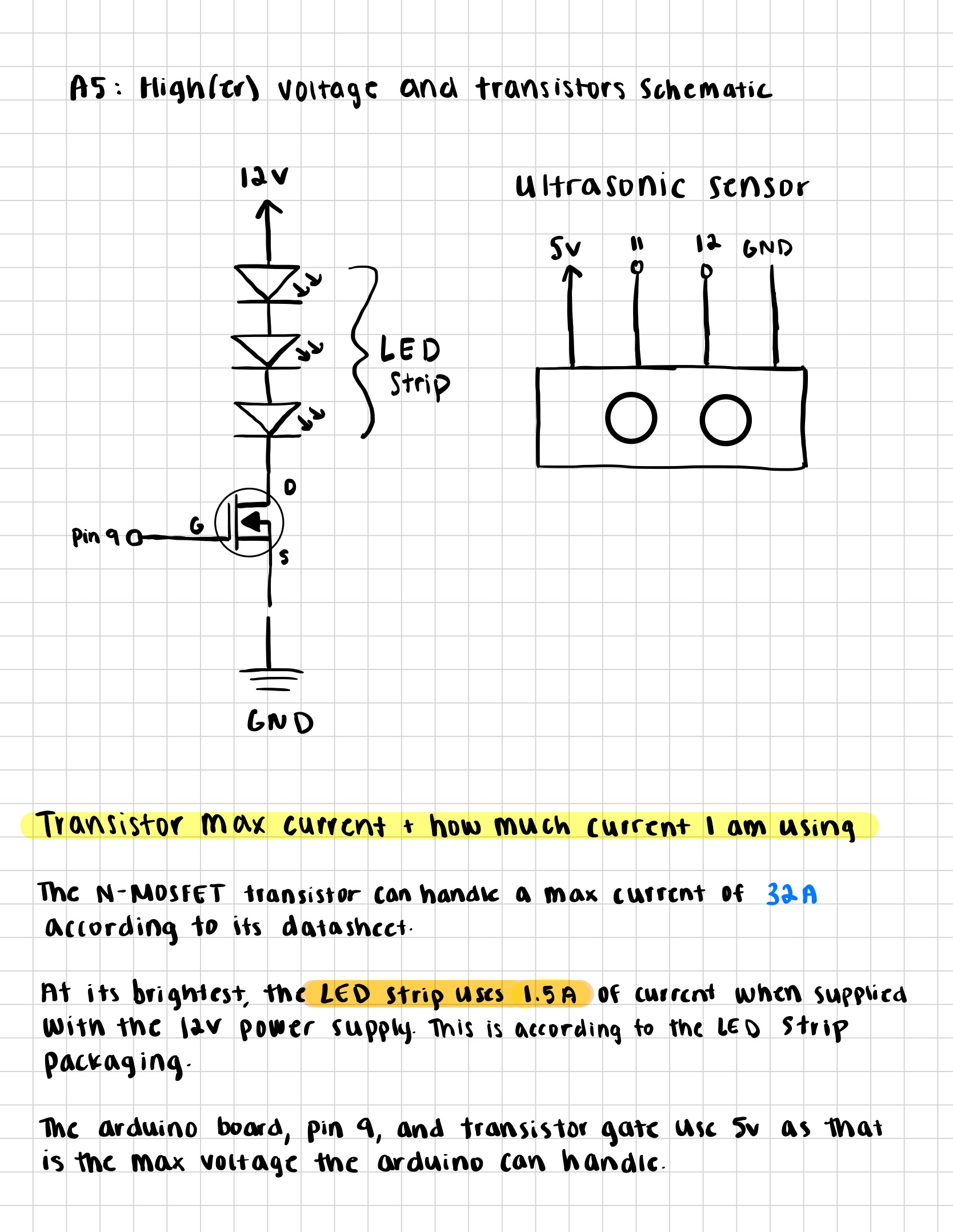
// define which Arduino pins are connected to the ultrasonic sensor and strip (through transistor)
const int trigPin = 11; // pin that sends out the trigger signal to the ultrasonic sensor
const int echoPin = 12; // pin that receives the echo signal from the ultrasonic sensor
const int ledPin = 9; // PWM pin connected to LED strip through transistor
// declare variables for timing, distance, and brightness
long duration; // stores the time it takes for the sound wave to travel to the object and back
int distance; // stores the calculated distance (cm
int brightness; // stores the LED brightness value (0 = off, 255 = fully on)
void setup() {
pinMode(trigPin, OUTPUT); // set the trigger pin as an output
pinMode(echoPin, INPUT); // set the echo pin as an input
pinMode(ledPin, OUTPUT); // set the LED pin as an output so Arduino can control it
Serial.begin(9600); // start serial communication for debugging
}
void loop() {
// Send a short ultrasonic pulse as the first step to measure the distance of an object
digitalWrite(trigPin, LOW); // make sure trigger pin is low to start the signal
delayMicroseconds(2); // wait for 2 microseconds
digitalWrite(trigPin, HIGH); // set trigger pin high to send a sound wave
delayMicroseconds(10); // keep it high for 10 microseconds because this is the required pulse length for the ultrasonic sensor
digitalWrite(trigPin, LOW); // set trigger pin low again to stop sending the pulse
// Measure the time it takes for the echo to return
// Get the time, in microseconds, that the echo pin stays high
duration = pulseIn(echoPin, HIGH);
// Convert the time to distance
// sound travels at ~0.034 cm per microsecond, divide by 2 (because it is traveling there and back)
distance = duration * 0.034 / 2;
// Limit and map the distance to LED strip brightness
distance = constrain(distance, 0, 50); // limit the measured distance between 0 and 50 cm to avoid extreme values
brightness = map(distance, 50, 0, 0, 255); // map distance (0 - 50 cm) to brightness (0 - 255), such that 0cm = LEDs off, and 50cm = LEDs fully bright
// Apply brightness to the LED
// send PWM signal to LED pin to control the brightness
analogWrite(ledPin, brightness);
// Print distance and brightness values to Serial Monitor
Serial.print("Distance: ");
Serial.print(distance); // show measured distance in cm
Serial.print(" cm | Brightness: ");
Serial.println(brightness); // show current LED brightness value
// Adding a short delay before starting the loop again
delay(100);
}