Assignment 2: Fade!

Here is all the documentation for assignment 2!

Schematic

Circuit Schematic Diagram Circuit Schematic Diagram

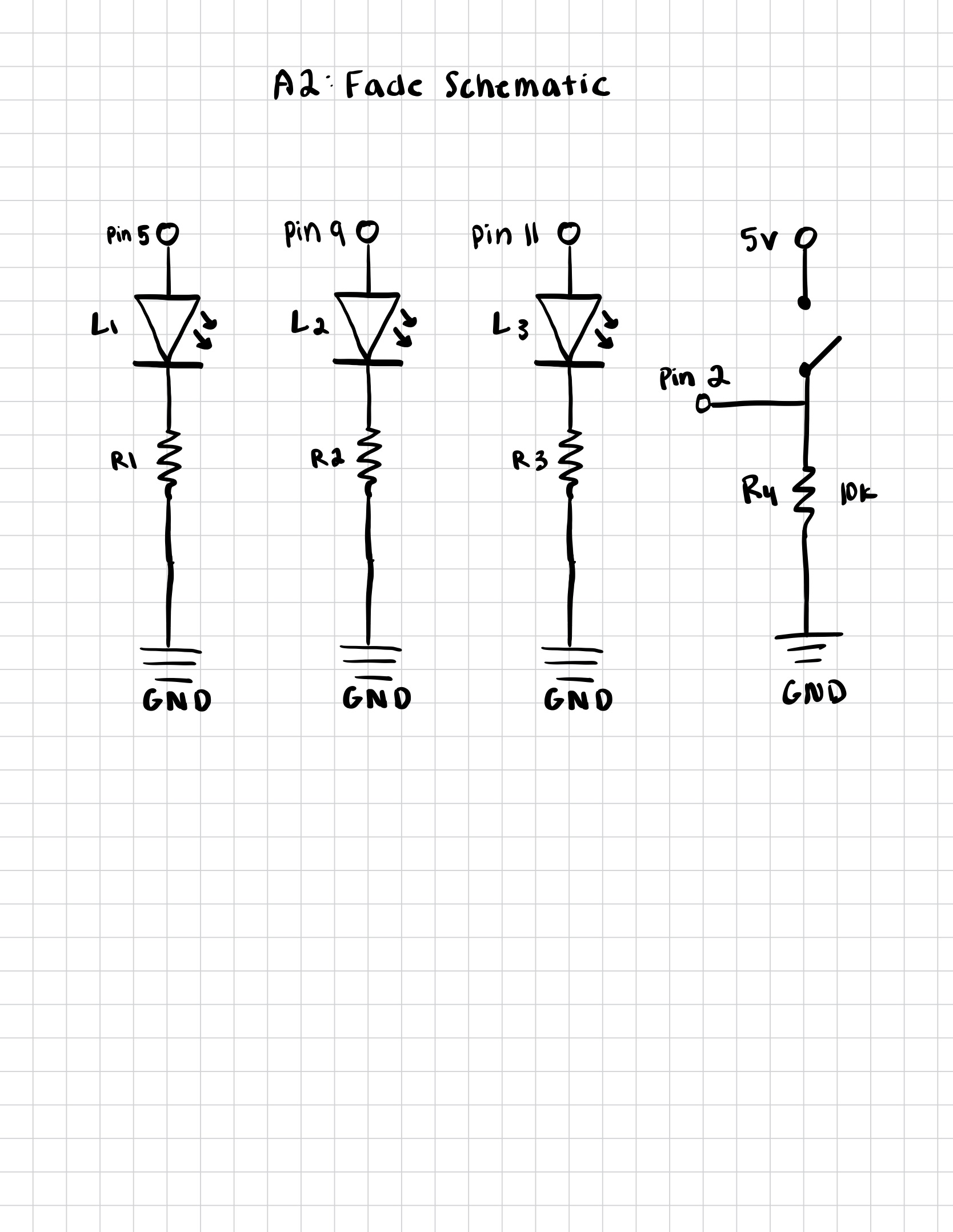
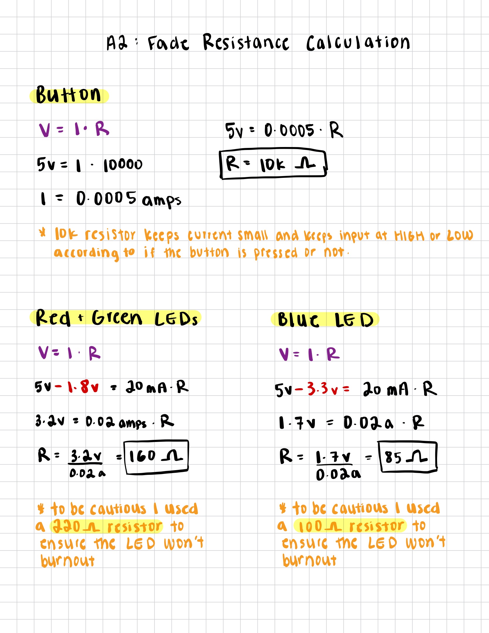
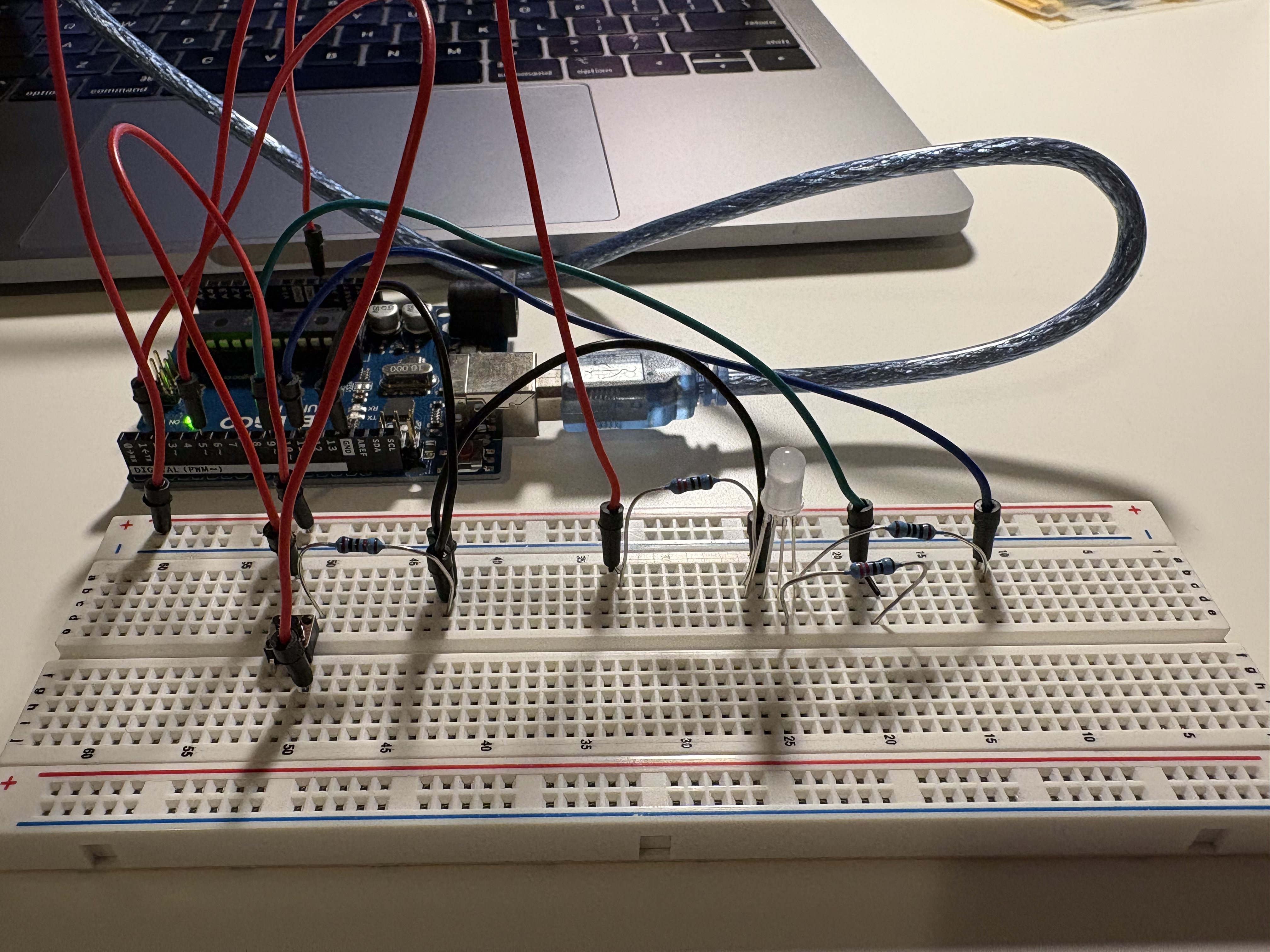
Schematic & Resistance Calculation Description: This schematic shows the circuit layout for assignment 2. Each LED was connected to a different pin on the Arduino. The resistances were calculated based on the voltage drop of the LEDs and the current required for each LED.

Circuit

Physical Circuit Setup

Circuit Description: This circuit connects an RGB LED and a pushbutton to an Arduino. Each color pin of the RGB LED (Red, Green, and Blue) is connected to its own pin on the Arduino through a current-limiting resistor. This allows the program to control the brightness and mix colors by varying the output signals. Pressing the button sends a HIGH signal to pin 2. The Arduino code can respond by cycling through different LED colors, fading effects, or brightness levels depending on the firmware!

Firmware

Arduino Code Screenshot

Code Explanation: This Arduino code fades an RGB LED through red, green, and blue color transitions only while a pushbutton is pressed. Each LED color pin is controlled with analogWrite() using PWM signals to vary brightness and create smooth color blending. When the button is released, all LEDs turn off using a helper function.

Circuit Operation

GIF Version: low quality :/

Animated GIF showing circuit operation

High Quality Video

Operation Description: The GIF and video above demonstrate the actual operation of the circuit. As shown, the LED only turns on when the buttons is pressed. If the button is held down, the LED will fade into different colors. When the button is released, the LED turns off!

Additional Questions

Questions 1 and 2

Graph showing voltage across LEDs over time

Graph Explanation: This graph illustrates how Pulse Width Modulation (PWM) controls LED brightness in an Arduino circuit. The X-axis represents time (ms) and the Y-axis represents voltage (V). Each colored line shows a square wave signal corresponding to a different analogWrite() value: Green line → 100% duty cycle, LED receives constant 5V, appearing fully ON. Red line → 50% duty cycle, LED is ON half the time, appearing at half brightness. Blue line → 25% duty cycle, LED is ON a quarter of the time, appearing dim.

Question 3: Actual Voltage vs. Theoretical Forward Voltage

Answer: The actual voltage I measured using my multimeter for a red LED was 2.2V. The theoretical forward voltage using a datasheet is 2.0V. The measured voltage is very close to the theoretical, with a slight tolerance!

Question 5: AI Tools Usage

Answer: How I Used AI Tools in this assignment: