// Arduino code for blinking three LEDs independently
/* For Loop Iteration
Demonstrates the use of a for() loop.
Lights multiple LEDs in sequence, then in reverse.
The circuit:
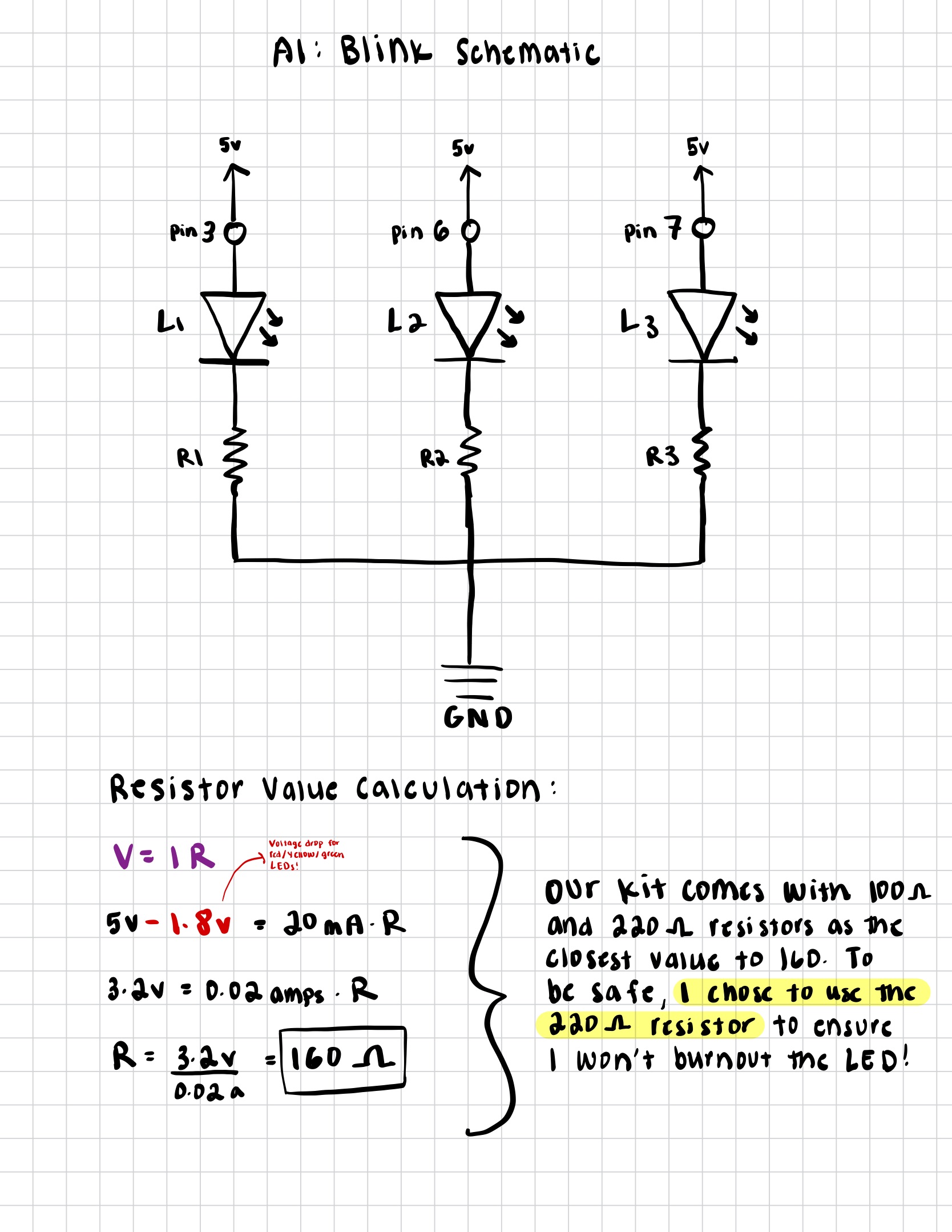
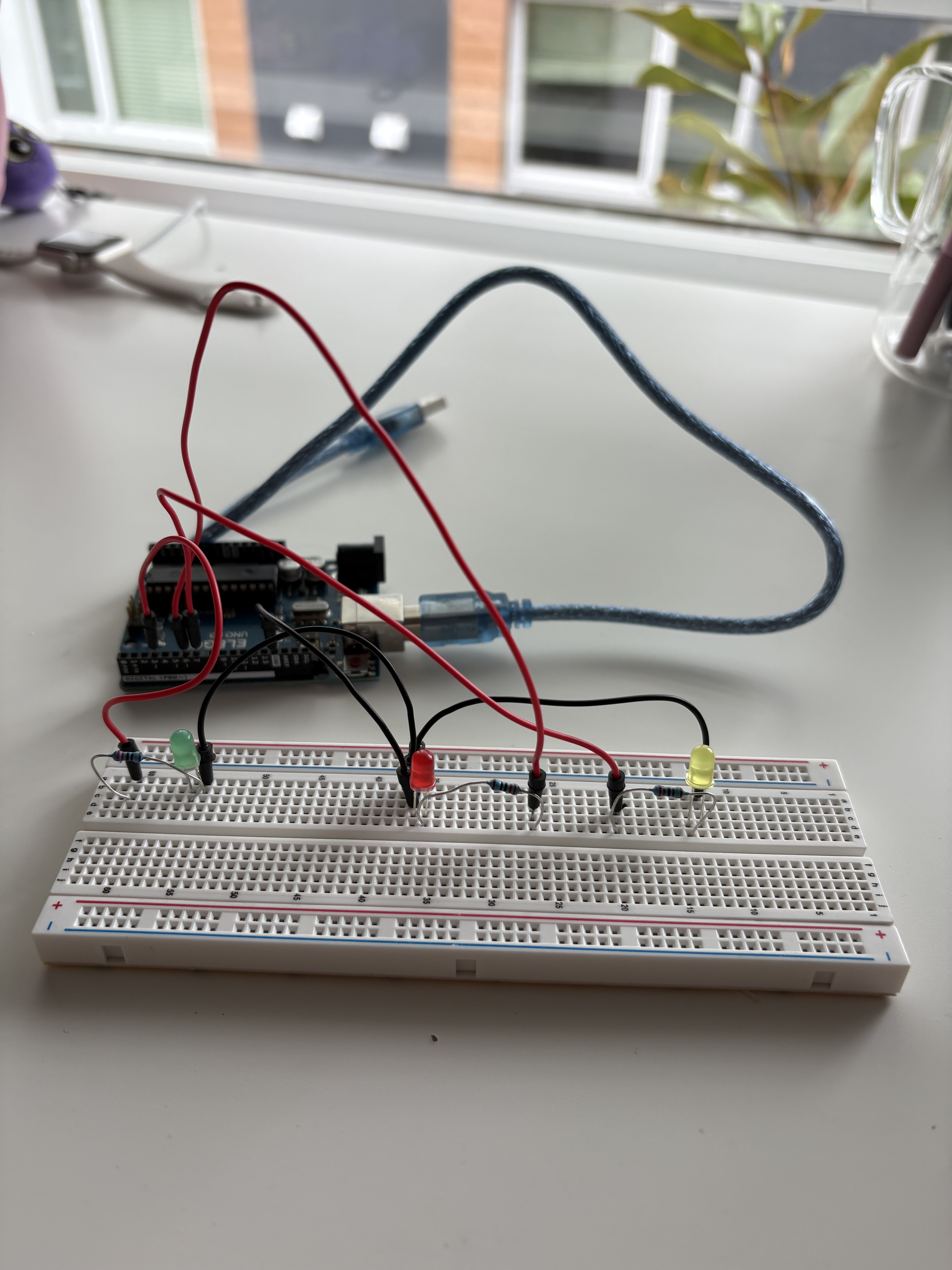
- LEDs from pins 2 through 7 to ground
created 2006
by David A. Mellis
modified 30 Aug 2011
by Tom Igoe
This example code is in the public domain.
https://docs.arduino.cc/built-in-examples/control-structures/ForLoopIteration/
*/
// Sets how long each LED stays on (in milliseconds)
int timer = 100; // Larger value = slower blinking speed
// The setup() function runs once when the program starts
void setup() {
// This for loop set each pin from 2 to 7 as an output pin (the pins I used for my
LEDS were 3, 6, and 7, so they are included in this range)
for (int thisPin = 2; thisPin < 8; thisPin++) {
// Configure pin as an output (so it can power an LED)
pinMode(thisPin, OUTPUT);
}
}
// The loop() function runs repeatedly forever
void loop() {
// The first loop will turn the LEDs on one by one from pin 2 to pin 7
for (int thisPin = 2; thisPin < 8; thisPin++) {
digitalWrite(thisPin, HIGH); // this will turn the LED connected to this pin on
delay(timer); // Wait for 'timer' milliseconds
digitalWrite(thisPin, LOW); // Turn the LED off before moving to the next one
}
// This second loop will turn the LEDs on one by one from pin 7 back down to pin 2
for (int thisPin = 7; thisPin >= 2; thisPin--) {
digitalWrite(thisPin, HIGH); // Turn the LED connected to this pin on
delay(timer); // Wait for 'timer' milliseconds
digitalWrite(thisPin, LOW); // Turn the LED off before moving to the next one
}
}
Code Explanation: This Arduino program uses for loops to make my LEDs
(connected to pins 2, 6, and 7) blink in sequence. Although I am only using three LEDs, the for loop
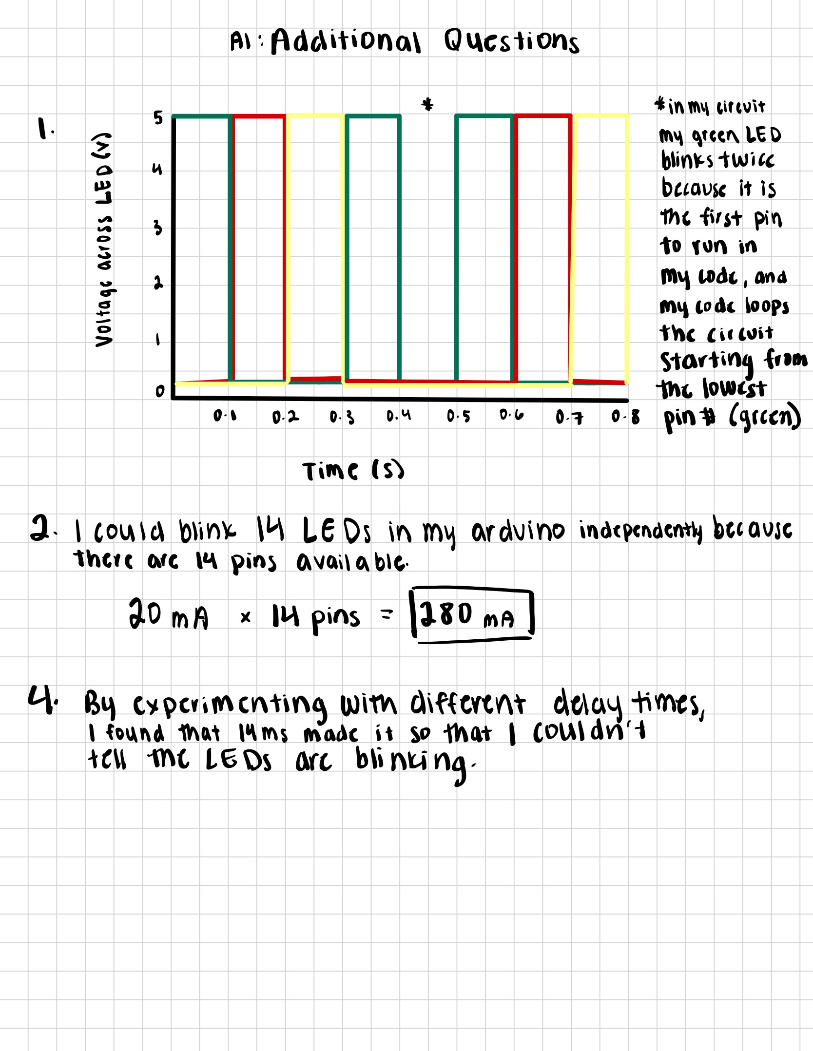
still works because it will just skip the pins that are not connected. In the first loop, each LED turns on
and off one by one from left to right. In the second loop, the LEDs light up in the opposite
direction, creating a back-and-forth chasing effect. The variable 'timer' controls how long
each LED stays on, which determines the blinking speed.